Project: Turbine Analysis
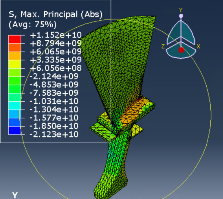
In this project I needed to model a turbine to determine the maximum stress and deflection in the blades, as well as determine the effects of resonance on the system. To maximize
software efficiency, I used radial symmetry when modelling the system. First, I started by modelling a single blade of the system and meshing the part. After that, I was able to apply various loads to determine the deflection and stress on each blade as a function of RPM.
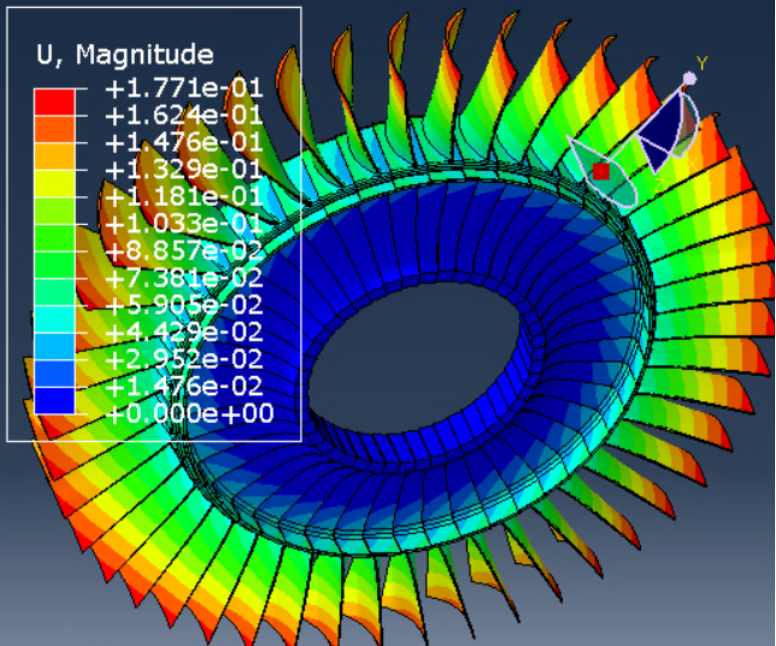
 Next, I used symmetry to model the entire turbine and visualize the blade deflections at the maximum operating speed of 20,000 RPM.
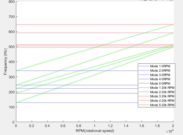
 The next step was to determine how vibration affected the turbine. Using Abaqus to perform a modal analysis, I was able to identify the first 5 modes and mode shapes at the minimum and maximum RPM's. By assuming that the modal frequencies change linearly with RPM, I was able to create a Campbell diagram showing the vibrational modes for the turbine blades as a function of RPM. In this graph, the green lines show the first 5 modal frequencies as a funtion of RPM.
 Finally - when overlaying this modal turbine data with the engine orders and turbine intake vane orders, the intersections represent the most dangerous frequencies for the entire engine assembly.
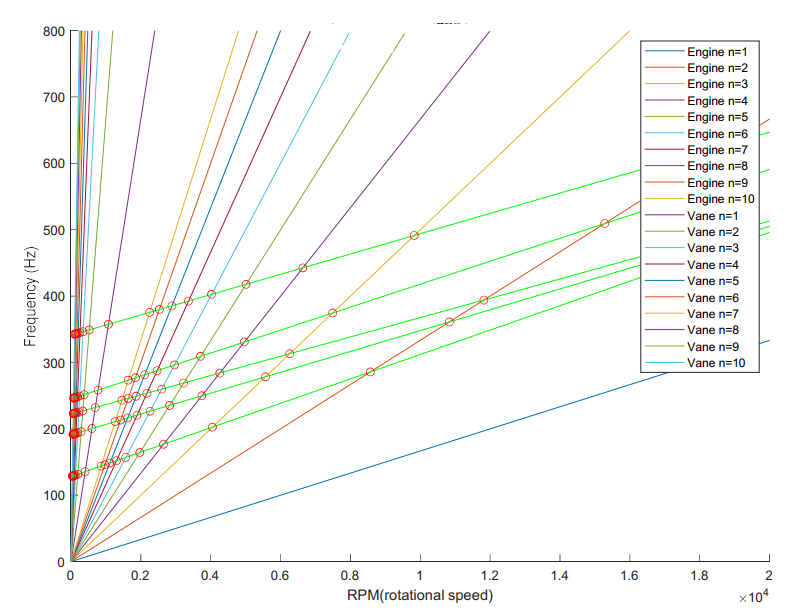 Each intersection is marked by a red circle and notes that a frequency must be dampened at the corresponding RPM in order to avoid resonance in the system between two or more components.